Interphone Paging System Wiring Diagram
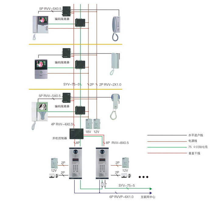
Wiring diagram for an interphone and pager system, showcasing the interconnection of various components. The diagram includes indoor monitors, outdoor stations, power supplies, and controllers.
Technical Specifications
System Overview
Interphone Paging System Connectivity
This professional-grade wiring diagram provides a comprehensive guide for the installation and integration of interphone and paging systems. It details the complex interconnection between indoor monitors, outdoor stations, power supplies, and central controllers. Designed for technical installers, the diagram ensures precise cabling and signal routing for reliable communication networks.
Wiring Specifications
Required Cabling Specifications
| Cable Type | Application |
|---|---|
| RVV-5x0.5 | 5-Pin Connection |
| RVV-4x0.5 | 4-Pin Connection |
| RVV-8x0.5 | 8-Pin Connection |
| RVVP-6x1.0 | 6-Pin Shielded Connection |
| RVV-2x1.0 | 2-Pin Power/Signal |
| SYV-75-5 | 75Ω Coaxial Cable |
System Components
- Supported Hardware
- Indoor MonitorsOutdoor Stations12V Power Supply18V Power SupplyParallel ControllersEncoding Isolators
Technical Standards
Network Features
- Horizontal wiring support
- Vertical trunk line integration
- Connection to central networking hub
- 75Ω coaxial cable signal transmission